The Tiger's firing circuit was typical of German tanks of its time, carried over from the Panzer III and Panzer IV. Its electrical schematic is in the Turret Manual. A distinction is drawn between the "old" turrets and the "new" ones.
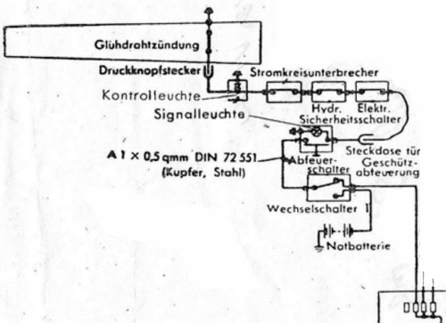
This is the firing circuit for "old" turrets [2, see Plate 59] . We will follow the circuit from where it leaves the distribution box at lower right.
Trigger wiring in the turret shell
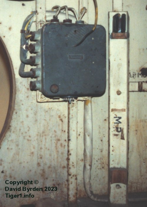
The distribution box is the standard "Kasten 5c". It isolates the firing circuit supply from those of the lights and the fan. All three wires leave this box via the top ports, and enter a sleeve which runs down to the turret ring and thus goes around the turret. (In the original "Initial" Tigers, the cabling ran around the top of the wall.)
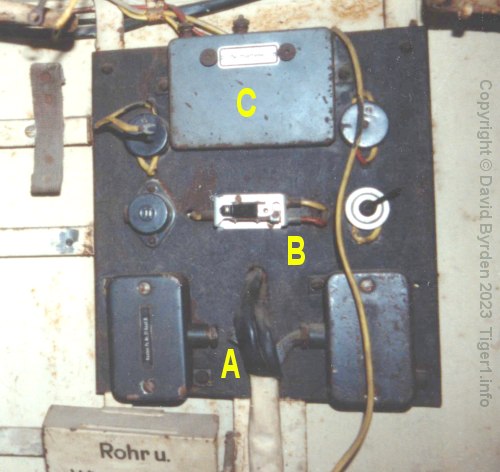
The wiring sleeve [A] then runs up from the turret ring to the turret circuit board. (Initial Tigers didn't have such a board, the items were fixed to the wall instead.) The firing circuit supply passes through the switch [B] on its right-hand side. [3]
The switch selects either the 12V supply that we have been following, or the 12V from the backup battery at [C].
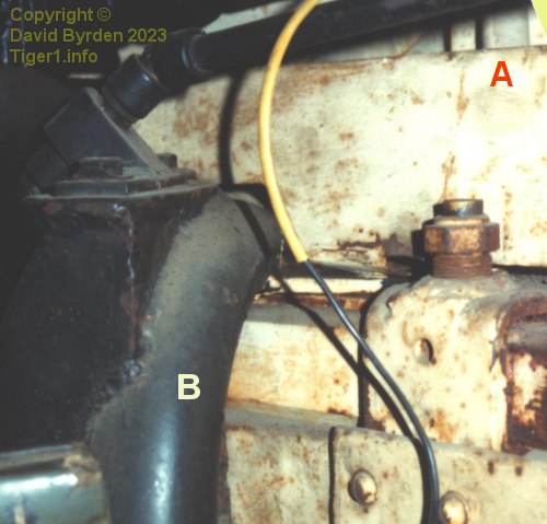
Emerging from the right side of the switch, the supply now runs back down inside the sleeve [A] to the turret ring, and then into the hollow structural tube [B] that is attached to the ring nearby.
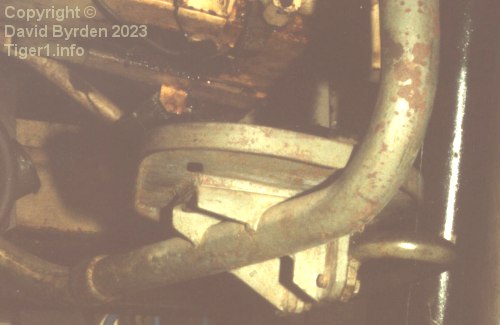
This photo, taken from outside the turret, shows that the tube runs down for a short distance then bends and runs across the turret space. The gunner's seat is attached to it. [3]
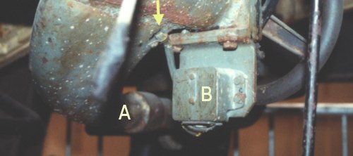
When it goes under the main gun, the supporting tube [A] flares out and bends upward. At this point the wire emerges from the tube through a tiny hole (arrowed) and goes to the trigger lamp at [B], which is marked "Signalleuchte" on the circuit diagram..
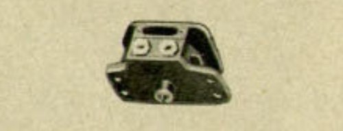
This is an image of the trigger lamp from a Tiger manual [1] . It has two glands for wires and a lamp behind a red window. In the Tiger it is fixed beneath the trigger with its lamp facing downward, which is unusual because the lamp directly faces the gunner in other Panzers. A protrusion on the bottom of this device has the trigger button at its end. Pressing this button will close the switch and illuminate the lamp.
In the Tiger, the device's output wire retraces the route of the input wire, back to the turret ring. This output wire carries the trigger signal itself; it will be 12V when, and only when, the gunner is pressing the trigger.
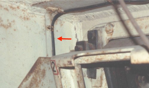
The signal wire, along with some other wires, now runs forward in a thin sleeve along the turret ring. Near the front of the turret, the sleeve runs vertically up the wall, and then across the roof.
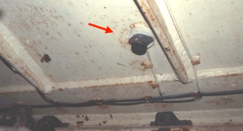
The signal wire breaks out of the sleeve and terminates in a standard electrical socket, named on the circuit diagram as a "Steckdose". A cable from the gun itself must be plugged in here to make the gun "live".
Trigger wiring for the smoke launchers
A smoke grenade system with electrical triggers was added very early in the Tiger's evolution. Its electrical triggers are not drawn anywhere in the Turret Manual.
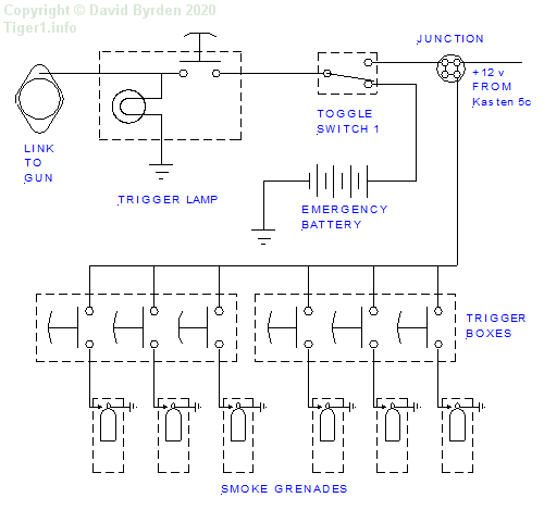
An examination of the preserved Tiger "712" reveals how the smoke grenade triggers were incorporated into the turret circuitry. A junction box was added to connect a lead to the 12V supply originating from the main battery. The six smoke launchers had a trigger button each.
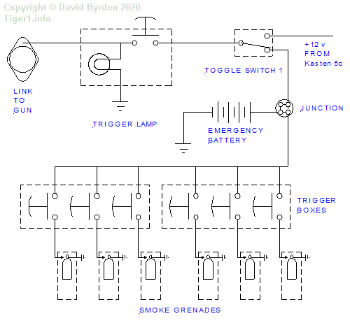
The turret was slightly revised after about 55 had been built [1] . This may have prompted a change to the wiring, because the circuit that I found in Tiger "131" was different to that in Tiger "712". Or perhaps the difference is due to the British engineers who disassembled "131"? In any case, Tiger 131's smoke launcher triggers were powered by the backup battery only when examined by me.
Trigger wiring in the gun
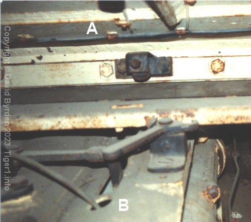
This photo of Tiger "131" is pre-restoration and everything has a layer of dust. The abovementioned socket is at [A]. The cable that should plug into it is lying loose on the gun. It enters the gun cradle through a hole at [B].
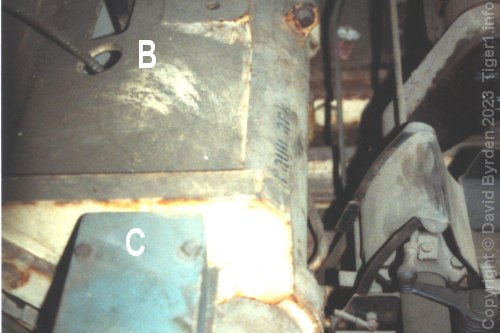
The cable runs a short distance inside the gun cradle and emerges through a small hole in the back wall, connecting to the blue safety switch [C]. The switch conceals the hole.
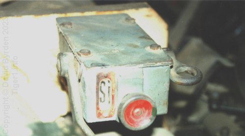
The safety switch, marked on the diagram as "Elektr. Sicherheitsschalter", allows the loader to give the "all clear" for each shot.
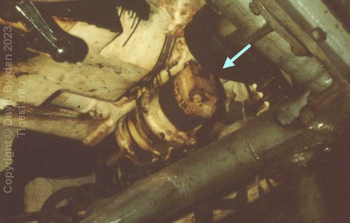
The output wire from the switch runs down inside the gun cradle and around the bottom of the gun sleeve, meeting no obstacles until it reaches this device.
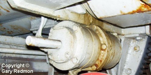
This is the "Hydr. Sicherheitsschalter", a switch that is closed only if the hydraulic recoil system is pressurised. We are looking at its left side now, and we can see that the signal runs through it, therefore two wires are connected to it. This example, in Tiger "712", has been painted white but is complete. If not for the paint, we could check the fluid pressure via a window in the protruding rod.
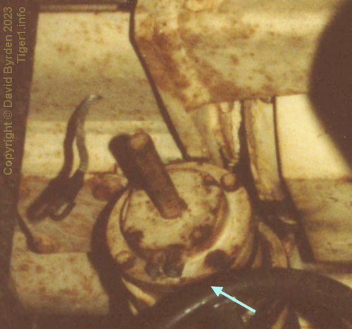
The example in Tiger "131" was taken apart by British engineers who reattached its cover wrongly; the two wiring ports (arrowed) should be on the forward edge, not the bottom edge. They also didn't reconnect the output wire, but we can see it going up into the gun cradle via a hole.
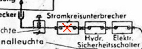
According to the circuit diagram, that wire should go to a circuit breaker ("Stromkreisunterbrecher"). But I cannot find such a device in any surviving Tiger, nor can I see a need for one. It would be wise to prevent firing if the gun is not returned all the way forward, of course, but there is a mechanical switch to guarantee that. I believe that this item on the circuit is a leftover from the very early days of the Tiger's design, and may have been installed only in the first few Tigers, if any.
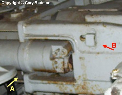
Skipping over the absent circuit breaker, the signal wire from the hydraulic switch should go to a "Kontrolleuchte" - an indicator lamp. The earliest German drawings show this lamp on the side of the gun's recoil guard, and that's where we find it in the surviving Tiger "712" which is a very early model. The wire passes through a hole [A] as mentioned before, goes up to the top of the gun cradle, through the back wall, and along the inside of the recoil guard. It emerges through a large hole to power the indicator light at [B].
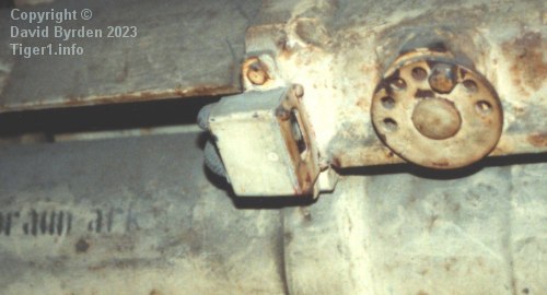
But in Tiger "131", which is a March 1943 build, that lamp has been moved forward to the gun cradle's rear wall. This is an improvement, making it more visible to the gunner, and we find it here in all subsequent Tigers.
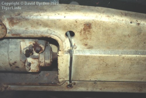
In Tiger "131" the original hole for the lamp is now used to get the signal wire to its next destination. Faint marks on the paint prove that the lamp was here when this Tiger was built; the improvement was made later. This kind of information is what we lose when vehicles are "restored".
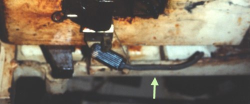
According to the circuit diagram, the signal wire now goes to a "Druckknopfstecker" or "push connector". This photo of Tiger "131" shows it. The wire from the prior photo passes into the bottom of the recoil guard and ends in a knurled cylinder.
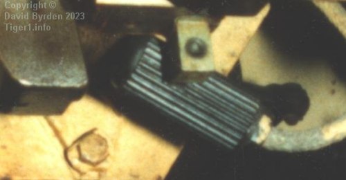
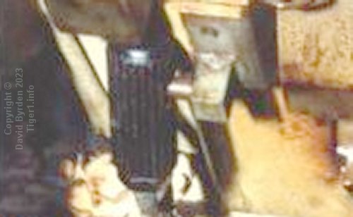
The "push connector" is another standard part (these photos are from a Panzer IV). It has a hole and is simply pushed onto a pin to make the connection.
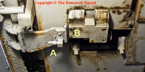
The modern white paint on Tiger "712" obscures various lamps and windows, but it also makes these small details easier to see. Here, we are looking at the gun breech from below [4] . The pin for the push connector is at [A]. It is on an arm fixed to the recoil guard. Above it is the gun's breech, which moves back and forward, and which contains the breech block [B] that moves down and up.
When the gun is returned fully forward after firing, and the breech block is safely closed, a spike connector in the breech block at [B], backed by a spring, makes contact with a metal surface on the arm. The trigger signal thus crosses the small gap that we can see here, entering the gun itself.
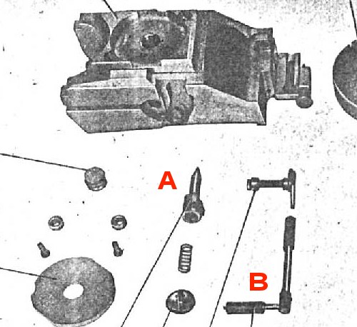
This image from a manual shows a Tiger breech block with some components removed. The spike connector is still visible in the block. An insulating "pencil" [B] sits inside the breech block, taking the signal up to another spike connector [A]. That connector presses against the rear center of the round's casing, bringing the trigger signal to where it can fire the round.
Subsequent changes to this circuit are discussed in an article about the new turret's circuit.
[1] Kraftfahrgerät teil 3, Fahrgestell und Turm Panzerkampfwagen "Tiger", heft 60
[3] Survey of Tiger 250122, at Bovington museum, by David Byrden
[4] A MODERN STUDY OF Fgst. Nr. 250031, by Lloyd, Balkwill and Johnson